![]()
![]()
![]()
![]()
![]()

![]()
![]()
|
|
|
|
INTERFACE BOARDS TO LET THE COMPUTER COMMUNICATE WITH INPUT/OUTPUT DEVICES
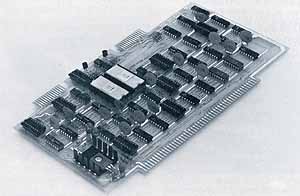
Serial 1/0 Interface SlO 2-2 The SIO 2-2 Serial I/O Interface hoard contains two identical ports, each permitting the computer to communicate with most peripheral devices through an RS232 or current loop interface. The two ports are independent. Each may operate through either the current loop or RS232 mode, and will operate in full-duplex or half-duplex with all control signals. You can run synchronous or asynchronous lines, full- or half-duplex, at any baud rate up to 9600 baud (asynchronous) or 56,000 baud (synchronous). Baud rates up to 9600 (asynchronous) or 38,400 (synchronous) are selected by jumpers on the board. Asynchronous baud rates are 75, 110, 150, 300, 600, 1200, 2400, 4800 and 9600. Synchronous rates are 1200, 2400, 4800, 9600, 19,200 and 38,400. Other rates are made possible using the SIOC board which mounts directly on the SlO board. Control lines for each input include DSR, DTR, RTS, CTS and Carrier Detect. RS232 receivers and drivers are also provided for clocks in synchronous operations. Jumpers permit using the board as either the receiving (terminal) end of a communication line or the originating (computer) end. Each interface is structured around an Intel 8251 USART chip. This chip allows extensive program control of I/O functions including control line and sync character selection, and error-condition sensing and recovery. The board generates interrupts for received characters, transmitter buffer empty, transmitter empty or sync character. A jumper selects the priority interrupt (acknowledged by the computer only if it includes the PIC-8 Priority Interrupt board). All functions may be program-controlled so that you can use the full capability of the board without using interrupts. The board may be jumper-adapted to respond either to I/O instructions from the IMSAI 8080 system or to memory reference instructions for memory-mapped I/O. If you need to change the data format or protocol in an RS232 line, you can easily connect an IMSAI 8080 in the line to intercept, process and retransmit the data. That's because jumper facilities let you use both of the serial I/O ports, with control lines connected together. Connector fingers on the upper edge of the board accommodate two flat cables (CABLE A) to connect directly to 25-pin EIA-type connectors, one for each port. No hand wiring is required to receive or originate an RS232 line. An edge connector EXPM is needed to install the SIO 2-2 board. One or two cables (CABLE A) are optional. Serial I/O Interface Board SIO 2-1 This is, essentially, an SIO 2-2 board containing chips for a single port. You can add another port later with the SIOM module. Serial I/O Module SIOM This set of components adds the second
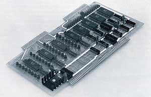
Parallel I/O Interface PlO 4-4 Use the Parallel I/O board as a custom TTL-level interface to peripheral devices. The board provides four 8-bit input ports, and four 8-bit output ports. Each input and output port has its own latch and handshaking logic for conventional parallel transfer. Handshaking logic on any I/O port will generate an interrupt, with the priority level of the interrupt selected on the board. (Note that the processor will not respond to the interrupt unless the computer contains the PIC-8 Priority Interrupt board.) The ports are addressed by four sequential addresses jumper-selected to be in the 256 I/O address space. You may also address the board with memory-mapped I/O, using normal memory read or write instructions to transfer data through the I/O ports. The Parallel I/O board includes a set of eight LED's for each output port (32 total). You'll find this useful for debugging, monitoring system activity, or replacing the front panel in dedicated applications. Mount a photographic mask, with appropriate legends, over the LED's to form a readable display. The front panel can still be used during development by plugging it into another slot. The board includes an IC regulator for the +5V supply, with tantalum capacitor filters on either side of the regulator. There is ample ceramic disk capacitor bypassing throughout the board. You can take +5V power (up to 300 mA total) from the +5V and ground pins on the I/O port connectors of a fully utilized board. For each unused port, an additional 100 mA maybe drawn from the board. If, for example, you are using four output ports and only two input ports, 500 mA is available from the board. On the top of the board, fingers accommodate two 50-pin connectors (25. pins per side on 0.1-inch centers) ,one for input ports, and one for output ports. An edge connector EXPM is needed to install the Parallel I/O board. P10 cables for input and output are optional. Parallel I/O Board PlO 4-1 This is a PlO 4-4 board containing components for one 8-bit input and one 8-bit output port. Expand it later with 1, 2 or 3 sets of components by adding PlUM sets. Requires edge connector EXPM. PlO cables for input and output are optional. Parallel I/O Module PIOM This is a set of components to add a single port to a PlO 4-1 board. Cable PlO Cable This cable connects parallel I/O signals between the Parallel I/O board and the rear of the IMSAI 8080 chassis. An edge connector attaches to the upper edge of the board and the cable divides into two 25-pin ETA-type female connectors which attach to the rear of the chassis. One PlO CABLE is used for all inputs and a second for all outputs.
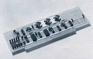
Universal Tape Cassette Recorder Interface UCRI-1 An audio tape cassette recorder is an inexpensive data storage medium. The UCRI-1 board modulates and demodulates an audio signal to read or write digital data. The board is connected to the tape recorder by two patch cords with RCA-type phone jacks (not supplied). The board lets you use either of two popular recording standards: BYTE or HIT. BYTE uses two different frequencies to designate a "1" or "0" bit. HIT uses a tone, or absence of tone, to designate the bit. The board communicates through four input and four output lines. Two are for "tape out" and one is for "tape in" signals. The others may be used for special circuits, such as turning the tape recorder on or off. The output lines may also be used to provide intermediate output levels approximating any desired waveform. That is, the unit can be used as a 4-bit digital-to-analog converter. Four additional resistors (not supplied) are required to provide this function. The UCRI-1 is driven by software. HIT standard software is furnished on punched paper tape, with source listings provided for reference. An edge connector EXPM is needed to install the UCRI-1 board. Interface Master Board IFM This will satisfy your need for an "intelligent" peripheral controller to get the best efficiency from your IMSAI 8080 system. It contains its own Intel 8080A microprocessor, a driver program in EPROM and a RAM buffer. Data is transferred between computer memory and the peripheral device at high speed by direct memory access (DMA). The EPROM program depends on the type of peripheral device you are to control. An IFM board is only available with the interface board for a specific peripheral device. Order an edge connector EXPM for installing the IFM board. DEC PDP 11/45 DMA Interface PDP/DMA This interface allows a Digital Equipment Corporation PDP 11/45 computer to communicate with an IMSAI 8080 computer at DMA speeds. It consists of a board that is inserted into a PDP 11/45 chassis, a board set for the IMSAI 8080 chassis, and an interconnecting cable. This feature allows IMSAI 8080 computers to be attached to a PDP 11/45 computer as satellite processors, yet be directly accessible to a PDP 11/45 program via its UNIBUS®. The IMSAI 8080 satellite processors may be used as work stations with terminals attached, nodes n a communications network, or as parallel processing units. Please contact the factory for additional information. Disk Drive Interface HDIF This interface enables the connection of a Disk-50, -80 or -200 drive to an IMSAI 8080 computer. Please contact the factory for additional information. General Purpose Interface Cables CABLE A, CABLE C CABLE A is a 15-inch, flat ribbon cable to carry signals from an interface board to a female 25-pin ETA-type connector (included) attaching to the rear of the chassis. A card edge connector (included) on the other end attaches to the pc board. Use CABLE A with SlO, FIF and LIF interface boards. CABLE C is a 5-foot ribbon cable for carrying signals between the rear of the IMSAI 8080 cabinet to a peripheral device, such as a floppy disk drive, modem or terminal. The cable has a male 25-pin ETA-type connector at each end.
|
|
When PCs Were Micros - Bits and pieces of history about the "good" old days
of microcomputers |