![]()
![]()
![]()
![]()
![]()

![]()
![]()
|
|
|
|
CHOOSE FROM ONE OF THE BASIC IMSAI 8080 MICROCOMPUTER SYSTEMS I-8080 The standard microcomputer includes:
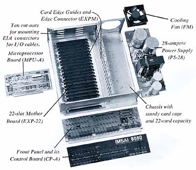
Mother Board Card-to-card spacing on the Mother Board is 3/4-inch, except for the first position reserved for the front panel board or any other board in dedicated applications. Additional four-slot Mother Board sections (EXP-4) may be added to accommodate connectors, and are connected to other Mother Board sections by jumpers between through-plated holes. A full-length, 22-slot Mother Board (EXP-22) is also available and may be ordered initially in place of the six-slot board. Heavy power traces handle the large currents that exist in a heavily loaded backplane. High-quality connectors have gold-plated contacts for reliability and long life. Front Panel The CF-A Board forms the operator's panel. It includes switches, indicators and logic needed for manual operation. The panel is completely self-contained and plugs directly into the first Mother Board slot. Or it may be connected through an extender board to any available slot in the Mother Board. When the first slot is not used for the front panel, that slot may be used by another board, such as the Parallel I/O Board with its LED indicators visible. Front panel facilities include:
The front panel includes logic that drives the programmed output indicators, and reads the input byte from the high-order address switches. DATA BUS indicators show data either read or written by the processor. Indicators are wide-angle LED's behind a contrast-enhancing acrylic panel assembly. Photographically produced panel markings are crisp and explicit and can never wear of f. Bit positions are numbered and labeled for both hexadecimal and octal notation. Special labels may be easily inserted to identify special functions for the programmed output LED's. Switches are high-quality units, with paddle handles color-coded for easy, error-free operation. Power Supply The Power Supply (PS-28) is designed for use with pc boards having on-board regulators. Outputs are + 1OV and ñ 18V at no load, and approximately + 7V and ñ l5.8V at full load. A Power Supply pc board contains rectifiers and 120V ac switching and fusing functions. The board provides terminals for switched ac power, both fused and unfused, for a ventilating fan and auxiliary power outlets ont he back panel. When the computer is supplied without the front panel, an AC power switch is mounted on the Power Supply Board. A custom-built transformer and large, conservatively rated filter capacitors are mounted on the chassis. Processor Board The Processor Board (MPU-A) contains the Intel 8080A Microprocessor chip, clock crystal oscillator and clock drivers, status signal latches and bidirectional bus drivers, as welt as on-board power supply voltage regulators. The bus arrangement and board connector are designed-so that the MPU-Aboard may be used directly in 4 the MITS Altair M8800 Microcomputer system. The 2-MHz, 2-phase non-overlapping clock for the processor chip is provided by an 18-MHz crystal and 8224 clock driver. An 8212 chip latches status signals. Two 8216 tn-state, bidirectional bus drivers interface the processor chip with the IMSAI 8080 data buses. Other tn-state bus drivers drive address, status and control lines. The MPU-A board receives ñ 16V and + 8V supply voltages and uses on-board regulators to obtain required voltage levels. The board edge connector has 100 pins on 0.125-inch centers, with 50 pins on each side. Except for gold-plated contact fingers, circuit traces are tin-lead plated for easier, more reliable solder connections. The board includes a power-on reset circuit, plus pull-up resistors so that without the front panel, power-on reset will start the program at location zero. Multiple microprocessor boards are able to share memory and run identical or different programs in parallel. I-8080-1K Same as basic I-8080 system with the 4 addition of 1K RAM memory on a RAM4A-1 board. Board may be expanded later by adding up to three MMO2-tmemory chip sets. Requires edge connector EXPM. I-8080-OEM Basic I-8080 system computer less front panel. Power on/off switch is provided.
|
|
When PCs Were Micros - Bits and pieces of history about the "good" old days
of microcomputers |