The Turbosupercharger and the Airplane Power Plant
General Electric
January, 1943
This pamphlet was published by General Electric, the builders of most U.S.
turbosuperchargers before and during World War II. This document was later published as
Technical Manual TM 1-404, dated 30 December, 1943. Translated to HTML format and
production Copyright © 1997 by Randy Wilson.
NOTE: To keep this document from loading too slowly, not all figures are
displayed. However, all figures are available to view by clicking on the linked Fig.
number. To return to this document, click on your browser's BACK button or arrow.
- General
- Rapid progress has been made in the last few years in the development and production of
military aircraft for effective high-altitude operation. High altitude precision bombing
and the advantage of full power at high altitude in combat have proved their value as
important elements of air supremacy.
- Airplane power plants of greater power output and reduced weight per unit of power
output are continually being produced.
- To understand thoroughly the important part played by the turbosupercharger in achieving
the above objectives, it is necessary to consider the source of power output of a gasoline
engine.
- Combustion
- The combustion, or burning, which occurs within a gasoline engine, is the source of
power which drives an aircraft. The carbon and hydrogen in the gasoline combine with the
oxygen in the air and the resultant vapor enters the engine. When such a chemical
combination takes place, the proportion by weight of the elements entering into the
combination is definitely fixed by chemical laws. As the composition of gasoline is very
uniformly 85 per cent carbon and 15 per cent hydrogen by weight, and air is 21 per cent
oxygen by weight, the weight of gasoline which will completely burn in a pound of air
without waste is definitely fixed. Fourteen and one-half pounds of air will support the
complete combustion of one pound of gasoline or, as more commonly expressed, 0.069 pounds
of gasoline per pound of air. It is necessary to have the right amounts of both fuel and
air in order to develop maximum power.
-
 If less than this weight of gasoline is supplied to the engine for
each pound of air supplied, we say that he mixture is lean. In this case, the oxygen in
the excess air can find no carbon or hydrogen with which to combine and, therefore,
performs no useful work in the engine. The power generated by the engine is accordingly
reduced below normal, since the available space in the cylinders is not fully used in
burning the fuel from which the power is derived. Reducing the rate at which fuel is fed
to the engine may be regarded as a form of throttling. If less than this weight of gasoline is supplied to the engine for
each pound of air supplied, we say that he mixture is lean. In this case, the oxygen in
the excess air can find no carbon or hydrogen with which to combine and, therefore,
performs no useful work in the engine. The power generated by the engine is accordingly
reduced below normal, since the available space in the cylinders is not fully used in
burning the fuel from which the power is derived. Reducing the rate at which fuel is fed
to the engine may be regarded as a form of throttling.
- When more than 0.069 pounds of gasoline is supplied to an engine for each pound of air
supplied, we say the mixture is rich. Some carbon and hydrogen in the excess gasoline will
pass through the engine in a gaseous form without being burned. As these gases could be
burned to perform work if sufficient oxygen (air) were present, there is a resulting loss
of combustion efficiency, which means poor fuel economy.
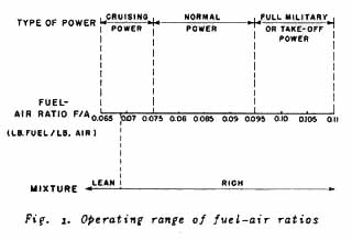
The mixture condition, or pounds of fuel per pound of air supplied to an aircraft engine
is called the fuel-air ratio or F/A. Fig. 1
shows the range of fuel-air ratios used with an aircraft engine. Note that an airplane
engine is usually operated on the rich side of the chemically correct fuel-air ratio
(0.069), and that a very considerable excess of fuel is used for take-off and full
military power. This excess fuel serves to cool the engine, and the engine tends to run
more smoothly with less danger of backfiring into the intake manifold. There is also an
increase in power with richer mixtures.
- It is evident from the above discussion that the performance of a gasoline engine is as
dependent upon the weight of air it receives as it is upon the amount or fuel supplied to
it. It is the intent of this manual to discuss the problems, and the solutions to the
problems, of supplying the aircraft power plant with the combustion air it requires for
maximum performance.
- Supercharging
-
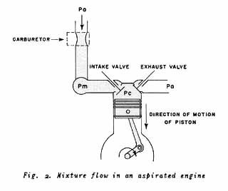 The conventional automobile engine is an unsupercharged engine.
In this type of engine, air fills the cylinder when the piston moves down. Power developed
depends on pounds of air in the cylinders. Supercharging, by in-creasing pressure, puts
more pounds of air in the same cylinder volume and, therefore, more power is developed.
Referring to Fig. 2, the amount of
mixture charge which flows into the cylinder during the intake stroke depends upon the
difference between the pressure in the manifold (Pm) and the pressure in the cylinder
(Pc). There must be a pressure difference between these two points to offset the pressure
losses caused by the flow of the mixture through the intake valve and to overcome the
inertia of the gases in the manifold. The pressure in the manifold is always somewhat less
than atmospheric pressure (Pa) because of the resistance to flow set up by the carburetor.
If the pressure of the mixture in the manifold (Pm) is increased by mechanical means above
the manifold pressure round in the unsupercharged engine, more mixture charge will flow
into the cylinder, with resulting increase in horsepower. The process of mechanically
increasing the manifold pressure is called supercharging, and where this is done the
engine is a supercharged engine. The conventional automobile engine is an unsupercharged engine.
In this type of engine, air fills the cylinder when the piston moves down. Power developed
depends on pounds of air in the cylinders. Supercharging, by in-creasing pressure, puts
more pounds of air in the same cylinder volume and, therefore, more power is developed.
Referring to Fig. 2, the amount of
mixture charge which flows into the cylinder during the intake stroke depends upon the
difference between the pressure in the manifold (Pm) and the pressure in the cylinder
(Pc). There must be a pressure difference between these two points to offset the pressure
losses caused by the flow of the mixture through the intake valve and to overcome the
inertia of the gases in the manifold. The pressure in the manifold is always somewhat less
than atmospheric pressure (Pa) because of the resistance to flow set up by the carburetor.
If the pressure of the mixture in the manifold (Pm) is increased by mechanical means above
the manifold pressure round in the unsupercharged engine, more mixture charge will flow
into the cylinder, with resulting increase in horsepower. The process of mechanically
increasing the manifold pressure is called supercharging, and where this is done the
engine is a supercharged engine.
- The Effect of Altitude on Engine Performance
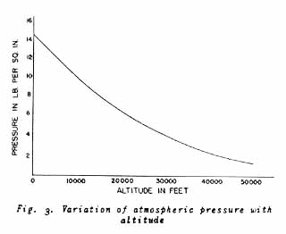
- The weight of the earth's atmosphere is sufficient to exert considerable pressure on
objects at sea level. At altitudes above sea level, the atmospheric pressure will be
lower. For example, the weight of air above the earth exerts a pressure or 14.7 pounds per
square inch on objects at sea level. The weight of air above 25,000 feet exerts a pressure
or only 5.45 pounds per square inch on objects at that altitude. Fig. 3 shows the variation of the
pressure of standard air with altitude.
- The density of air is the weight of a cubic root of air. Density of air depends upon its
pressure and temperature. (The effect of temperature on density will be discussed later.)
The greater the pressure of the air, the greater is the weight of a cubic foot of air. The
less the pressure, the less the air weight per cubic foot. At 25,000 feet, a cubic foot of
air weighs only 45 per cent as much as a cubic foot of air at sea level. It was stated
that the engine required an adequate weight of air, in order to develop its rate output.
As the altitude at which an aircraft is flown is increased, the air pressure becomes less,
and the density, or pounds of air per cubic foot, becomes less. If the engine is to
maintain its rated horsepower at increased altitudes, it must take a much larger volume of
air from the atmosphere surrounding it, in order to keep the weight flow from decreasing.
- Because of limitation of cylinder displacement, which is a measure of volume, the
unsupercharged engine cannot handle greater volume of air as altitude is increased.
Therefore, the horsepower output of such an engine decreases with altitude.
- By properly supercharging an engine, the weight of air flow to it can be maintained at
the point of rated power output. This is done by mechanically pumping air from the
atmosphere surrounding the aircraft into the engine manifold, at the pressure required, to
obtain the rated power output or the engine.
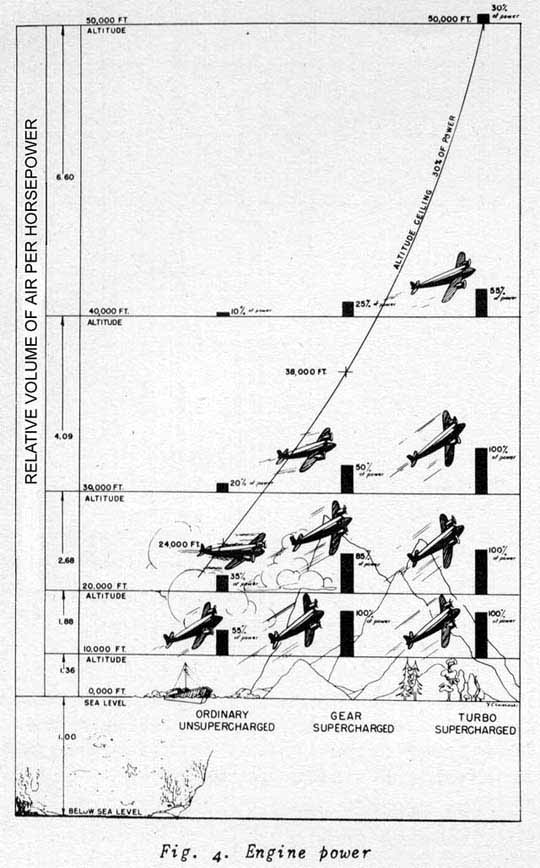
- While an aircraft can fly at altitudes where the output of its power plant is
appreciably less than its rated sea-level value, the speed, maneuverability, and rate of
climb or the plane decreases as the power drops off. The diagram in Fig. 4 gives a graphic comparison of the
performance of typical unsupercharged and supercharged aircraft with respect to altitude
of flight. In this diagram, it is assumed that the ceiling at which an airplane can be
flown with sufficient stability and maneuverability is the altitude at which the power
plant output is 30 per cent of its rated sea-level output. The height of the black columns
represents the power available to the propeller at the respective altitudes. The spacing
of the altitude lines is in proportion to the volume of air required by the engine to
produce 1 hp, as is indicated in the column to the left of the figure.
- Advantages of Full Power at Altitude
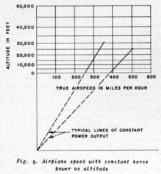
- The speed of an aircraft, which can maintain its rated power output, increases as the
altitude at which it is flown is increased. This is true because the air resistance, which
limits the speed of the airplane, decreases as the density of the air in which it is flown
decreases. The adjustable-pitch propeller maintains its thrust in the lighter density air
by taking a larger bite with each revolution. Fig.
5 shows how the speed of an airplane will be increased by flying at higher
altitudes, if the power output or the engine is maintained constant. This effect of
increased speed may be used on a military mission to reach the objective more quickly, or
may be used as an element of superiority over enemy aircraft which are not able to
maintain full power at the altitude or combat.
- By use of the turbosupercharger, it is usually possible to fly at the particular
altitude and speed which will result in maximum over-all efficiency. This means that less
fuel would be required for each mile travelled, and the range of the airplane would be
increased. In the case of a bomber, the savings in fuel requirements could be made up by
an increased bomb load.
- The ability to fly at high altitudes will permit the airplane to fly above much bad
weather which might otherwise have to be circled.
- Flying at high altitude greatly reduces the hazard of antiaircraft fire and the
possibility or effective attack by interceptor planes. This factor is of particular
importance for the period of flight before the plane reaches its objective.
- Methods of Supercharging
- A supercharging system suitable for full-engine-power operation at high altitude must be
able to take in air at high-altitude density and pressure, compress it, and deliver it to
the engine intake manifold at the required pressure (and, therefore, at the right
density). Either a pump or a blower may be designed to do this. When the proper condition
of pressure is created in the intake manifold, the weight flow of the mixture into the
engine cylinder will be adequate.
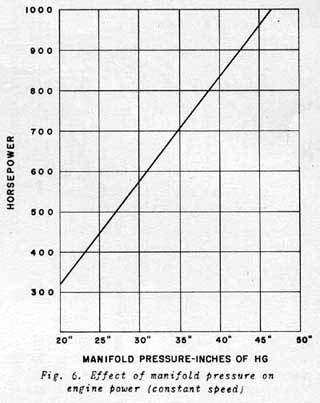
- The engine manifold pressure, being a measure of the weight flow of the fuel-air mixture
to the engine cylinders, is also a measure of the power output of the engine running at a
constant speed. Fig. 6 shows the
relative effect of manifold pressure on the power output of an engine. From this figure it
is evident that increasing the manifold pressure (supercharging) is a most effective way
of greatly increasing the horsepower output of an engine without increasing its size and
weight.
- It is very important to note that, during warm-up or flight operation, the maximum
manifold pressure specified by the engine manufacturer must not be exceeded. Excessive
manifold pressure will force so great a weight charge of mixture into the engine that the
power output, internal heat, and mechanical stress within the engine will be greater than
that for which the engine was designed. This overstressing of the engine would greatly
reduce its life of operation and might result in immediate engine failure. This is a
frequent cause for burning up cylinders and blowing off cylinder heads.
- Operation recommendations provide for use of high manifold pressure and maximum power
for short periods of time. This "military" or "take-off.' power is used
when high power is required for take-off or to meet a military emergency in combat.
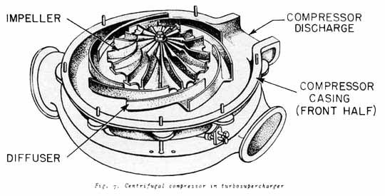
- The characteristics of the centrifugal compressor make it the most effective type for
aircraft-engine supercharging. This type of compressor operates most effectively at high
speeds, and has the ability to compress a large volume of air at low pressure. Because the
centrifugal compressor runs at high speeds, its size is relatively small and its weight is
light. It also has minimum moving parts, and the problems of lubrication and maintenance
are thereby minimized. The centrifugal compressor consists of three basic elements -- the
impeller, the diffuser, and the casing. Air enters the impeller at the center and is
discharged radially at the ends of the blades with high velocity energy. The diffuser
converts this energy to pressure energy. The casing collects the air under pressure for
delivery to the engine induction system. Fig. 7
shows a centrifugal compressor with half of the casing removed to expose the impeller and
diffuser.
- Superchargers
- Internal Superchargers
- A supercharger which is located between the carburetor outlet and the intake manifold of
the engine is called an internal supercharger. A supercharger thus located serves to
provide a uniform distribution of the fuel-air charge to the various cylinders, as well as
to increase the density of the charge. Maintaining a high manifold pressure ahead of the
intake valves allows the use of "valve overlap" in the engine, so that the
intake valve opens just before the exhaust valve closes at the end of the exhaust stroke.
This allows the compressed mixture from the intake manifold to scavenge the spent gases
out of the clearance volume of the cylinder and also tends to improve the cooling of the
exhaust valve. This cooling is of particular importance when operating at
"military" or "take-off" power. With no supercharging between the
carburetor and the intake valves, "valve overlapping" would permit exhaust gases
to flow back into the intake manifold. This would cause backfiring and dilution of the
next charge of mixture with burned exhaust gases.
- An internal supercharger is always used to obtain maximum performance from modern
high-power aircraft engines and high-grade fuels. The internal supercharger is built into
the airplane engine and is called a geared supercharger.
- The power required to drive the geared supercharger is taken, through a train of gears,
from the engine crankshaft. Thus, the net power output available to drive the propeller is
decreased by the amount which is taken from the crankshaft to drive the geared
supercharger.
- External Superchargers
- A supercharger located ahead of the carburetor in the induction system is called an
external supercharger. An external supercharger is used primarily to obtain full-power
engine performance at high altitudes, and is generally driven by an exhaust-gas turbine. A
supercharger so driven is called a turbosupercharger. In a turbosupercharged power plant,
the high-altitude air is compressed to approximately sea-level pressure before delivery to
the engine carburetor. The temperature of the air passing through the compressor of the
turbosupercharger is considerably increased as the result of the compression. This effect
of temperature increase is similar to the increase in the temperature of the barrel of a
tire pump during use.
- If the temperature of the air entering the engine exceeds certain limits, detonation
(knocking) will occur in the engine. This detonation would cause a sharp decrease in the
power output of the engine, and would greatly overstress parts of the engine. The
temperature limit of the carburetor-inlet air at which detonation in the engine will occur
depends upon the design of the particular engine and the temperature rise in its internal
supercharger.
- Also, the density (weight per cubic foot) of the air charge again enters the picture. As
the temperature of the entering air is increased, its density becomes less. To offset the
temperature rise due to compression, an intercooler is installed between the
turbosupercharger air discharge and the carburetor inlet.
- This intercooler is similar in its operation to the conventional automobile radiator,
except that the transfer of heat is from the compressed air to the cooling air instead of
from water to the cooling air. The cooling air is taken from a "ramming" air
intake on the aircraft and is fed by means of ducts through one series of passages in the
intercooler. Hot air from the turbosupercharger is fed through another series of passages,
running in a cross-direction to the cooling air. These two paths of air flow are separated
by thin metal walls, and the heat transfer takes place through these walls.
- Cooling air leaving the intercooler is normally ducted to a discharge opening in the
aircraft structure. Shutters or doors are located in the cooling-air circuit so that the
pilot can control the temperature of the air entering the carburetor by varying the amount
of cooling air used in the intercooler. In practice, the intercooler is so designed that
the maximum temperature of the air which enters the carburetor will not exceed a
relatively high sea- level temperature (90 F to 100 F).
- The engine exhaust is connected directly to the nozzle box of the turbosupercharger with
a gastight stack. In order that the energy in the hot exhaust gases may be used to furnish
the power which is used by the turbine to drive the turbosupercharger, it is necessary to
build up the pressure in the exhaust stack and nozzle box sufficiently, so that the gases
will acquire a high velocity when expanding through the nozzles of the turbine down to the
pressure of the atmosphere in which the airplane is flying. Tests have shown that the
pressure built up in the exhaust stack by the turbine is almost the same as the pressure
built up in the carburetor by the compressor, and is normally about sea-level pressure,
regardless of altitude at which the airplane is flying. Thus, under normal conditions of
operation, the engine would receive its charge at sea-level density and would exhaust at
sea-level pressure. Therefore, the engine will develop sea-level horsepower up to the
rated altitude of the installation. In brief, the turbo-supercharger supplies an
artificial sea-level atmosphere to the engine.
- The turbosupercharger may be used to increase rated engine power at sea level, or to
furnish "ground boost", as well as to maintain rated power at high altitude.
Although the turbosupercharger speed required for this purpose is much less than the rated
speed, it is necessary to build up the engine exhaust pressure appreciably above the
atmospheric pressure at sea level, and other low altitudes, in order to furnish turbine
power. The amount by which this exhaust pressure can be increased without unduly affecting
engine operation will depend upon the particular engine in question. It is very important
that the instructions covering the specific aircraft involved be closely followed in the
operation of a turbosupercharged power plant.
- Turbosuperchargers
- At the present time, turbosuperchargers are used in series with geared superchargers,
the intercooler and carburetor being located between them. In this way, maximum use can be
made of the advantages of each type.
- A geared supercharger has one obvious advantages of compactness, lightness, and ease of
installation. The greatest disadvantage of the geared supercharger is its application for
high-altitude flight is its inflexibility of speed. If it is designed to develop sea-level
pressure at 20,000 feet, for example, it will deliver an excessively high pressure at sea
level with the carburetor throttle opened wide, so that the throttle must always be
partially closed for low-altitude operation. However, since the speed is not reduced, the
supercharger drive still subtracts from the power available to the propeller, an amount
approximately equal to the power taken at rated altitude. In an effort to reduce these
difficulties, two-speed and two-stage geared superchargers have been designed and built.
These are better than the single-speed, single-stage machine, but they necessitate an
increase of size, weight, and complexity. No matter how many stages or different gear
ratios are used, such a geared supercharger can never have the perfect flexibility of
speed control of a turbosupercharger, and must always involve some waste of power when
operating below the altitude for which it was designed. The speed of the turbosupercharger
can be controlled to maintain desired conditions of carburetor-inlet pressure without
regard to the engine speed.
- Operating Characteristics
-
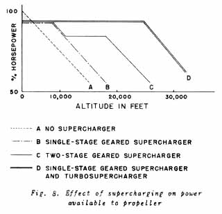 The operating characteristics of engines equipped with various
types of superchargers is shown on the general altitude-vs-engine-horsepower diagram of Fig. 8. The line (A) indicates the
variation in horsepower of an engine built without an internal supercharger or a
turbosupercharger. As illustrated, the power begins to fall off as soon as altitude is
increased. The plane can fly to considerable altitudes, but the power is so reduced that
finally a point will be reached where there is insufficient power to maintain the plane in
level flight. The operating characteristics of engines equipped with various
types of superchargers is shown on the general altitude-vs-engine-horsepower diagram of Fig. 8. The line (A) indicates the
variation in horsepower of an engine built without an internal supercharger or a
turbosupercharger. As illustrated, the power begins to fall off as soon as altitude is
increased. The plane can fly to considerable altitudes, but the power is so reduced that
finally a point will be reached where there is insufficient power to maintain the plane in
level flight.
- Line (B) shows the approximate characteristics of an engine equipped with a single-stage
geared supercharger. In this case, there is some reduction in power at sea level because
some of the engine power is required to drive the supercharger and, hence, is not
available to the propeller. This deficiency in power over that of an unsupercharged engine
is overcome very shortly as altitude is increased, and nearly constant power continues to
the critical altitude of the geared supercharged engine, which is in the order of 6000
feet to 7000 feet. Beyond this altitude power diminishes as altitude is increased, but the
altitude at which the plane will continue in level flight is greater than that of an
unsupercharged engine.
- Line (c) shows the characteristic of a two-stage geared supercharger and, here again,
the altitude at which engine power begins to fall off has been advanced, because of the
higher pressure ratio obtainable when two stages of compression are employed. Somewhat the
same effect can be obtained by single-stage, two-speed super chargers. In either of these
combinations, however, the critical altitude where the power begins to diminish is at
about 18,000 feet.
- Line (D) indicates the characteristic of a plane equipped with single-stage
internal-supercharged engines and turbosuperchargers. The power available to the propeller
is still the same as obtained from a single-stage supercharged engine, and this power
continues to an altitude of approximately 25,000 feet. Beyond the critical altitude, there
is sufficient power to maintain flight to altitudes of at least 35,000 feet.
- The Turbosupercharged Power Plant
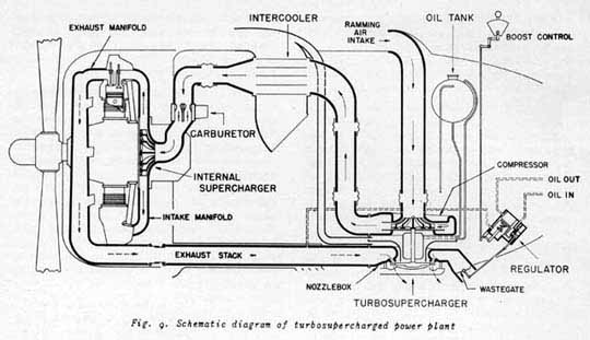
- It is well to consider the turbosupercharged power plant with reference to the part
played by each of the elements which go to make up a turbosupercharger system. Fig. 9 is a schematic diagram of a
complete turbosupercharger system.
- Air, which will eventually be supplied to the engine to support combustion, is taken
into the system through what is called a "ramming" air intake. This intake is
usually located on the leading edge of the engine nacelle or wing, and is designed to take
full advantage of the velocity of the plane through the air or the force of the air
velocity of the propeller wash, to obtain what is, in effect, a small amount of
supercharging in the intake itself. This air is directed to the inlet of the compressor of
the turbosupercharger where the first compression of the air is made. The amount of the
compression depends upon the speed at which the turbosupercharger is operated, and the
compression ratio may be as high as 2.86 to 1. This means that atmosphere taken into the
compressor at an altitude of 25,000 feet with apressure of approximately 11 inches of
mercury, may be discharged from the compressor with a pressure of approximately 50 inches
of mercury. As a result of this compression, the temperature of the air leaving the
compressor would be sufficiently high to cause detonation, if fed directly to the
carburetor. For example, if the entering air is -30 F at an altitude of 25,000 feet, the
temperature of the air leaving the compressor would be approximately 150 F. To reduce this
temperature, the air is passed through the intercooler before going to the carburetor. As
mentioned before, this cooling also serves to increase the density of the air charge. The
mixture of the air and fuel takes place at the inlet to the geared supercharger. The
temperature of the mixture leaving the carburetor is somewhat less than the entering air
temperature, because of the removal from the air of the heat requiredd to vaporize the
fuel.
- The mixture charge from the carburetor is then fed to the inlet of the gear-driven
internal supercharger. In this second stage of compression, a compression ratio of
approximately 1.5 to 1 at rated engine speeds is normally used. With the moderately low
compression ratio of this stage, the temperature rise of the mixture is not excessive, but
sufficient pressure is maintained to assure uniform distribution of the mixture to the
cylinders and to allow the use of "valve overlap" for exhaust-gas scavenging and
exhaust-valve cooling.
- Hot exhaust gases from the cylinders are collected in manifold or collector ring through
the exhaust stack to the nozzle box of the turbosupercharger. The nozzles are designed to
allow the gases to expand, and, thereby, to reach high velocities before striking the
buckets of the turbine wheel. Exhaust gases which are not required to drive the turbine
are by-passed through a waste gate to atmosphere before reaching the turbine nozzles. This
completes the cycle of the air required by the engine or combustion as it is passed
through a turbo-supercharged power plant.
Fig. 10 shows pressures and
temperatures encountered in a typical turbosupercharger application operating at 25,000
feet.
- Description of Turbosupercharger
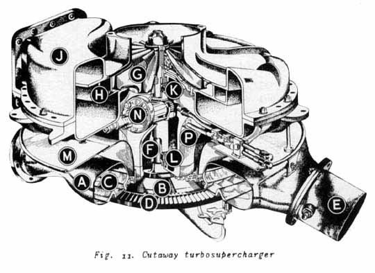
- Fig. 11 shows a cutaway view of a
typical turbosupercharger. This is simply a high-speed centrifugal compressor driven by a
turbine which derives its power from the hot exhaust gases of the engine. The exhaust
stack connects to the nozzle box (A), which is directly above the turbine wheel (B). The
hot gases escape from the nozzle box through fixed nozzles (C). The nozzles permit an
expansion of the exhaust gases which increases velocity and directs it against the buckets
(D) on the turbine wheel. The high speed and power of the turbine are the results of the
flow of these high-velocity gases against the turbine buckets. The speed of the
turbosupercharger is controlled by allowing excess gases, not required for turbine
operation, to escape through the waste gate (B), instead of through the turbine nozzles
and turbine wheel. With the waste gate closed, all the gases will go through the turbine,
and it will revolve with maximum speed and power. With the waste gate wide open, the
turbine will idle.
- The power developed is transmitted through the shaft (F) to the impeller (G) of the
centrifugal compressor, which is mounted on the opposite end of the shaft. Engine air is
ducted from a ramming air intake on the leading edge of the wing or front of the nacelle
to the inlet of the compressor. The impeller (O) and diffuser (H) are enclosed in a
suitable housing called the compressor casing (J), which collects the compressed air from
the diffuser. The rotating assembly is supported by ball and roller bearings which carry
the thrust and static loads imposed. The ball bearing (K) is located on the impeller end
of the shaft, and takes the thrust load of the shaft, which is in the direction of the
impeller when the turbosupercharger is running. The roller bearing (L) allows for
expansion of the shaft.
- The baffle ring (M) assures the proper distribution of the turbosupercharger cooling air
between the nozzle box and the compressor casing. The baffle ring also serves as a shield
to prevent the transfer of heat from the nozzle box to the compressor casing by radiation.
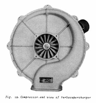
- The turbosupercharger is lubricated by a built-in oil pump (N), which is driven by a
worm gear from a worm sleeve keyed to the shaft. The pump and bearings are enclosed by the
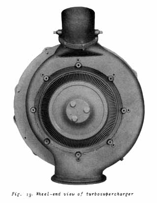
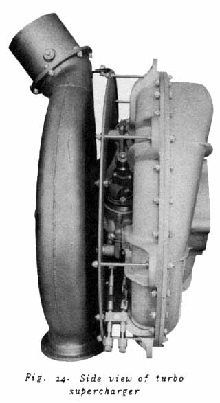
bearing-and-pump casing (P). The turbine wheel is cooled by a cooling cap. The standard
type of cooling cap is of the convection type, and directs cooling air from the aircraft
slipstream against the turbine wheel. Fig. 12,
13, and 14 show the completed turbosupercharger
assembly.
- Lubrication of Turbosuperchargers
- Lubrication pump
- The turbosupercharger lubrication pump is really two separate positive-displacement
pumps on the same shaft. One of the elements of the pump supplies oil to the gears and
bearings. The other element is a scavenging pump which removes oil from the housing and
returns it to the supply tank.
- There is a tachometer connection on the end of the pump shaft, from which the speed of
the turbosupercharger can be determined.
-
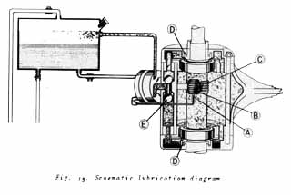 Fig. 15 is
a schematic diagram of a turbosupercharger lubrication system, using a separate oil tank.
The oil for lubricating the turbosupercharger from the oil pump enters the inside of the
bearing and pump housing through a shroud (A) which lubricates the pump drive gear (B).
The oil is transferred from the shroud by the drive gear to the mesh of the drive gear and
the worm thread sleeve (C). The bearings are oiled by the splash from the drive gear, and
by the oil mist which exists inside of the bearing housing as a result of the high
rotation speeds and churning of the oil. This combination of splashing and oil mist is
ideal lubrication for the ball and roller bearings. Some turbosuperchargers are designed
with jets which deliver oil directly on the ball and roller bearings. This provides no
better lubrication than the oil mist, but it does provide for more efficient cooling of
the bearing. Fig. 15 is
a schematic diagram of a turbosupercharger lubrication system, using a separate oil tank.
The oil for lubricating the turbosupercharger from the oil pump enters the inside of the
bearing and pump housing through a shroud (A) which lubricates the pump drive gear (B).
The oil is transferred from the shroud by the drive gear to the mesh of the drive gear and
the worm thread sleeve (C). The bearings are oiled by the splash from the drive gear, and
by the oil mist which exists inside of the bearing housing as a result of the high
rotation speeds and churning of the oil. This combination of splashing and oil mist is
ideal lubrication for the ball and roller bearings. Some turbosuperchargers are designed
with jets which deliver oil directly on the ball and roller bearings. This provides no
better lubrication than the oil mist, but it does provide for more efficient cooling of
the bearing.
- The capacity of the scavenging element of the pump is about three times that of the
pressure pump at all times. Because of this, two thirds of the scavenging-pump delivery is
air. The pumping of this air causes a slight vacuum in the bearing housing, which is
necessary to prevent oil leakage through the shaft oil seals. The two shaft oil seals (D),
one on the turbine end and the other on the compressor end of the bearing housing, are not
rubbing seals, but have a clearance from the shaft of 0.002 in. to 0.005 inches. These
seals are threaded to cause an inward flow, which tends to keep the oil inside the pump
and bearing casing. This action is assisted by the vacuum which is created inside the
casing by the excess capacity of the scavenging pump.
- The dumbbell valve (E) operates by gravity. The intake of the scavenging pump is through
this valve, and the valve position will always be such that the scavenging-pump intake
will draw only from the bottom of the bearing and pump housing, regardless of the position
of the plane in flight.
- Turbosuperchargers are usually installed with a separate oil-supply tank of about one to
two gallons capacity, which is normally about 75 per cent full of oil. The excess volume
of the tank is necessary to accommodate any foaming of the oil which may be induced by the
scavenging pump.
- The rotor of the turbosupercharger operates at extremely high speeds compared with
speeds normally encountered in other equipment -- 21,300 rpm for a rated altitude of
25,000 feet for one type. At this speed, the balls in the ball bearing, for example, are
rotating at approximately 60,000 rpm about their own axis. Bearings which will stand up
under these extreme conditions of speed are of special design, and are manufactured with
extra-fine precision. It is obvious that special care must be used in the handling and
fitting of these bearings during overhaul operations. It is also of utmost importance that
no foreign matter be allowed to get into the lubricating-oil system, and that
recommendations on the oil used and the method of operation of the turbosupercharger be
closely followed.
- Turbosupercharger Coo1ing Requirements
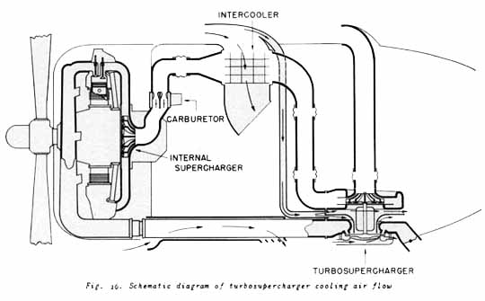
- Fig. 16 shows a schematic diagram
of the various paths of cooling-air flow required in a normal turbosupercharger
installation. Cooling air is required for the exhaust-stack shroud, the turbine-wheel
cooling cap, the back of the turbine nozzle box, the compressor casing, the bearings, and
the intercooler.
- The exhaust stack is that part of the exhaust system which conducts the exhaust gas from
the engine collector ring or exhaust manifold to the turbine nozzle box. In the exhaust
stack are one or more flexible joints to allow for thermal expansion and engine vibration.
The usual design of the exhaust stack includes a ventilated shroud which is a concentric
pipe surrounding the exhaust stack, and which is ventilated by a rammed-cooling-air blast.
This exhaust-stack shroud serves the dual purpose of forming a fire wall around the
high-pressure exhaust stack, and providing a means for precooling the exhaust gases before
entering the turbine nozzle box.
- The convection-type cooling cap delivers cooling air to the rim of the turbine wheel at
the point of attachment of the turbine buckets to the wheel blank. The air is discharged
on the trailing edge of the wheel, to avoid recirculation of the air over the wheel.
- The bearings, compressor casing, and back of the nozzle box are cooled by a duct which
delivers air radially inward toward the center of the turbosupercharger. This air stream
is divided by the baffle ring, with approximately 40 per cent of the air passing between
the baffle ring and nozzle box, and the remainder between the baffle ring and compressor
casing.
- The volume of intercooler cooling air required is normally about double the amount of
the engine air which is cooled. Flaps or shutters, located downstream from the intercooler
in the cooling-air stream, provide a control of the air temperature entering the
carburetor.
- The turbosupercharger cooling air is taken aboard where full use can be made of the
propeller slipstream, or of the velocity of the plane, to assure adequate air supply and
distribution. Care is taken in locating the cooling-air ducts, so that minimum heat will
be picked up before the air reaches the turbosupercharger or intercooler. In particular,
the cooling-duct intakes are located so that no hot exhaust gas or discharged
engine-cooling air will be rammed into the cooling passages.
- Turbosupercharger Regulation
- One of the advantages of the turbosupercharger is flexibility of control. The speed of
the turbosupercharger rotor and, consequently, the pressure supplied to the engine, is
controlled by changing the amount of exhaust gases that pass through the nozzles to drive
the turbine wheel. Opening the waste gate allows more exhaust gases to be bypassed, and
the rotor speed is decreased.
Conversely, closing the waste gate will increase the rotor speed.
- A hydraulic regulator automatically moves the waste gate to hold the nozzle-box pressure
constant at the value determined by the position of the boost-control lever in the
cockpit. By changing the setting of the regulator, the proper exhaust pressure and
corresponding manifold pressure can be obtained for the desired engine power, such as
cruising, normal or military power.
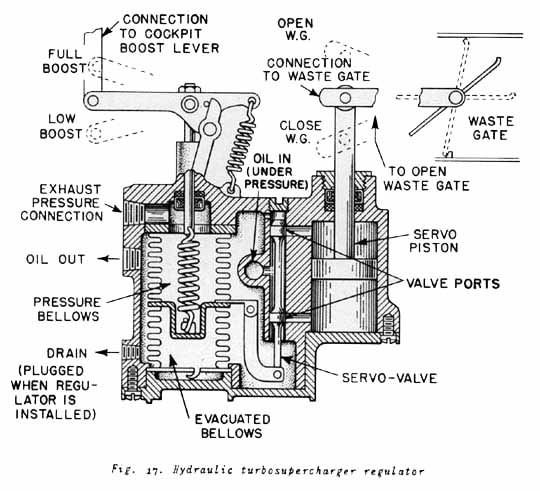
- Fig. 17 is a diagram of a typical
hydraulic regulator. There is a tube leading from the nozzle box to the top bellows. The
bottom bellows is evacuated and serves to prevent the top bellows from acting in response
to atmospheric changes in pressure. Inside the top bellows is mounted a spring, one end of
which is connected to the junction between the two bellows, and the other end to the
range-shifting control lever. This lever is connected by linkages to the cockpit boost
control. The purpose of the spring and control-lever assembly is to allow the pilot to
vary the pressure on the spring for different nozzle-box pressure, corresponding to
different engine powers. This spring tension just balances the pressure in the top bellows
to the point where the servo-valve ports to the servo piston are closed.
- As pressure changes occur in the top bellows, they act on the servo valve and shift its
position, thereby opening ports which direct oil under pressure into one side of the
piston. The piston then moves under the unbalanced oil pressure, and moves the waste gate
with it. The servo piston continues to move the waste gate until the pressure in the
nozzle box has been corrected. When corrected, the pressure in the bellows restores the
servo valve to its closed-port position, and stops the piston motion.
- The regulating process, described above, occurs in a very short space of time, a few
seconds at most. Therefore, in actual operation, as soon as the exhaust pressure starts to
change, the hydraulic regulator starts to move the waste gatem a direction to counteract
this change. That is, for a given setting of the cockpit boost lever, the regulator always
acts to maintain a constant exhaust pressure, and the actual exhaust pressure varies from
this constant value only temporarily during those few seconds required by the hydraulic
regulator to move the waste gate in a direction which restores the pressure.
- For some pursuit airplanes equipped with turbosuperchargers, the size of the evacuated
bellows in the regulator is reduced. This causes the atmospheric pressure to have some
effect on the upper bellows and results in a slightly decreasing nozzle-box pressure with
increasing altitude. This type of regulator holds an approximately constant manifold
pressure without changing the setting of the boost control lever up to the airplane's
rated altitude.
- Installation Considerations
- Induction System
- The design and construction of the induction system is of primary importance in the
application of a turbosupercharger system. The induction system carries the required
engine air from the slipstream to and through the compressor element of the
turbosupercharger, then through the intercooler to the engine carburetor.
- Mention has been made of the use of rammed-air intakes. These intakes are specifically
designed to take the required weight flow of air on board the airplane with the least
disturbance of the slipstream over the air foil section. The "rammed-air
intakes" are preferably located on the leading edge of the wing or engine cowl. When
air scoops, which project from the surface of the aircraft are used, the trailing surface
of the scoop is appropriately streamlined so that minimum drag is introduced. Because of
the forward motion of the plane, the "rammed-air intakes" tend to increase the
pressure at the inlet to the compressor. This gain in pressure achieved by the
ramming-engine-air intake, is particularly important in the turbosupercharged power plant,
because this gain is multiplied by the compression ratios of the two stages of compression
which follow.
- The duct from the ramming-air intake usually consists of two or more sections of pipe
connected by flexible joints. These flexible joints are installed between the compressor
and the ramming-air intake to isolate vibration of the ship structure from the high-speed
turbosupercharger compressor. These flexible connectors are also incorporated between the
turbosupercharger compressor and the intercooler, and between the intercooler and the
carburetor-air intake. In the case of the connecting duct to the carburetor inlet, the
motion of the engine in its dynamic mounting must also be isolated by the flexible
connectors. Such flexible connectors usually consist of a neoprene or synthetic-rubber
sleeve which is band-clamped to the abutting end of the duct section.
- Another factor in the design of the induction system is to minimize the pressure losses
resulting from sharp bends, rapid changes in cross section, and use of undersize ducts.
Usually the airplane design dictates the path of the induction system. The best use must
be made of the space available to keep the induction-system losses low.
- Since the internal pressure of the induction system at high altitudes is as much as 10
to 11 pounds per sq in. greater than the external atmospheric pressure, the design
requires that the induction system withstand a pressure differential of 20 pounds per sq
in., without leakage. Any leakage which develops in the system represents a loss, and
detracts from the efficiency of the installation.
- The installation of an inter-cooler of the proper size and design is important in
maintaining the efficiency of the turbosupercharged power plant. The intercooler should
provide adequate cooling of the air discharged from the compressor, to assure the proper
charge density. At the same time, the inter-cooler should not be of excessive weight, and
should not offer too great a resistance to the engine air flow in the induction system.
- The exhaust system of the turbo-supercharged power plant carries the exhaust gas from
the cylinders to the nozzle box of the turbosupercharger. This piping must also contain
flexible joints to isolate vibration, and also to allow for expansion caused by heat. It
is very important that the exhaust piping shall exert no stresses on the nozzle box. If
stresses are allowed, the nozzle box will be distorted. During high-altitude operation,
the pressure inside the exhaust manifold may be 10 to 11 pounds per sq in. greater than
the atmospheric pressure. Again care must be taken to prevent leakage. Leaks in the
exhaust system will always tend to enlarge because of the high temperatures of the exhaust
gases. In normal installations, the exhaust stack is encircled by an exhaust cooling
shroud. Cooling air is forced through this annular passage. Gases leaking from the exhaust
pipe will leak into this space, and not into the plane structure. Leakage of the exhaust
gases will detract from the power available to drive the turbosupercharger, and will
thereby reduce the critical altitude of the installation.
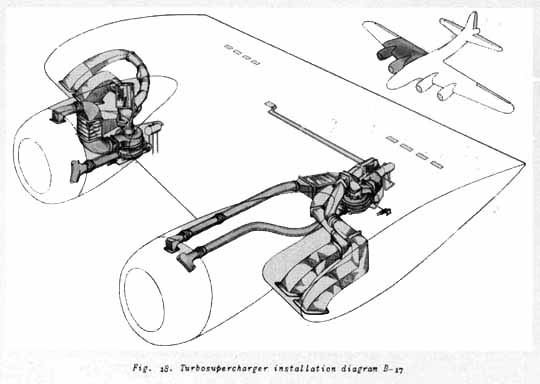
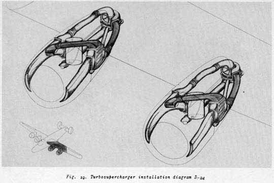
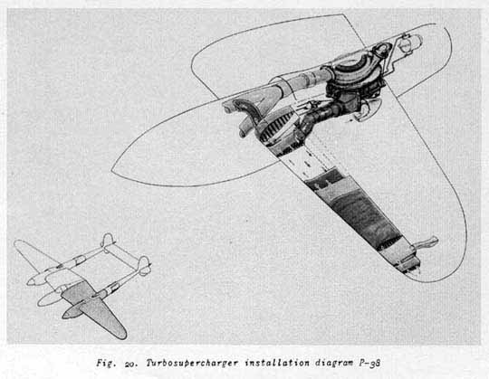
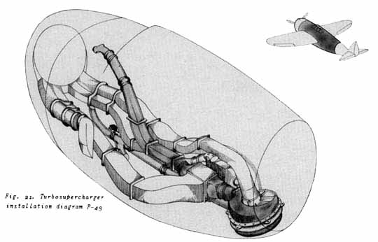
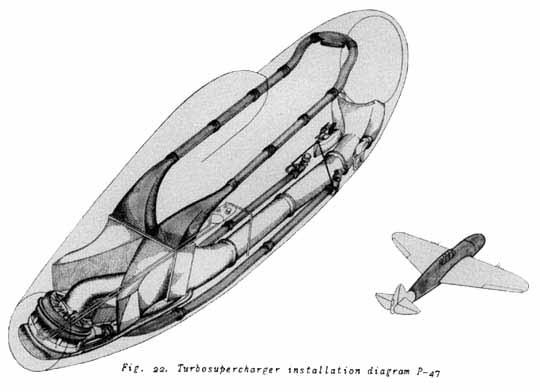
- Fig. 18, 19, 20,
21, and 22 are schematic diagrams of typical
turbosupercharger applications.
- Care and Maintenance of Turbosuperchargers
- Turbosupercharger installations require very careful inspection and maintenance in
service. The turbosupercharger, although very simple in construction, operates at very
high speeds. Very great differences in temperature are prevalent in a relatively small
piece of equipment.
The effective operation of the turbosupercharged power plant depends upon the efficient
operation of all its component parts.
- Specific instructions for inspection and maintenance are covered by Technical Orders
covering this type of equipment. A brief summary of the items which require daily
inspection follows:
- Check the turbosupercharger, exhaust system, induction system, intercooler, and control
system for security of mounting and evidence of failure.
- Inspect the turbine buckets for distortion or other evidences of failure.
- Check clearance between turbine wheel and nozzles.
- Inspect and lubricate the waste gate.
- Check the oil supply for correct amount, and inspect the lubrication system for leaks.
- Immediately, at beginning engine run-up, determine that the turbine wheel is rotating
freely. Check operation of the regulator to determine if sluggish.
- Turbosupercharger overhaul, as well as any other repairs involving disassembly of the
unit, should be made only at air depots. To avoid damage to the unit, the instructions
covering the removal of the turbosupercharger from the airplane should be carefully
followed.
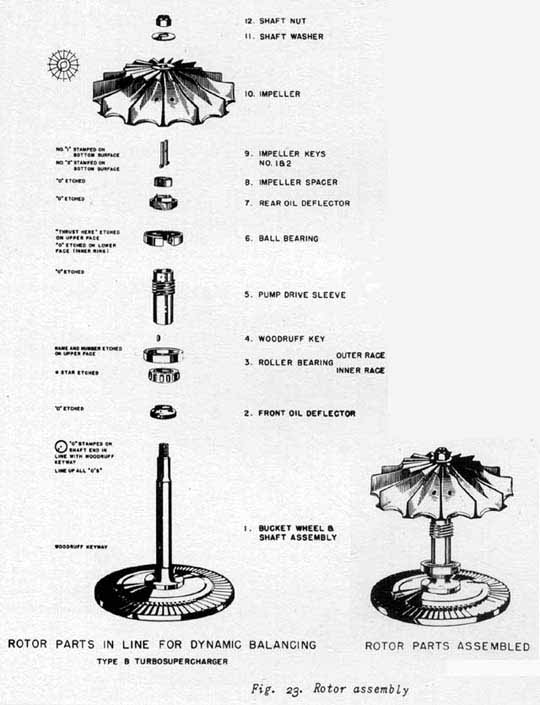
- Bearing replacement is recommended procedure on each normal overhaul.
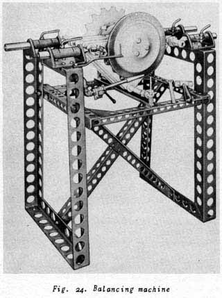
- The supercharger parts having been reconditioned, the complete rotor assembly, Fig. 23, must be dynamically balanced,
in accordance with the detailed instructions of the Army Air Forces Technical Orders
covering this subject. Fig. 24 shows
the balancing machine used for this purpose. Balance of the impeller end of the rotor is
obtained by removing material at the scallops of the impeller. The turbine-wheel end of
the rotor is balanced by removing material (by grinding) from the inner face of the
turbine wheel.
The nozzle box is made of corrosion resistant steel, and repairs involving welding are
made with a type of welding electrode approved by the manufacturer. This electrode is
coated, so that the resulting weld has practically the same properties as the welded
material.
- Operation
- A turbosupercharger aircraft must be operated in strict accordance with the specific
instruction provided in the Army Air Forces Technical Order for operation of each type of
airplane. Operation may be discussed in a general manner by considering the
characteristics of the turbosupercharger and the effect of the turbosupercharger on the
aircraft power plant under different conditions of flight operation.
- Starting
The engine should be warmed up in the usual manner. The turbosupercharger regulator should
be in the OFF position so that the waste gate is in the open position. Particular care
must be taken to avoid any backfiring which may distort the waste gate or balloon the
nozzle box.
- Take-off
After warm-up of the engine, set the propeller at the rpm specified for take-off, then
open the throttle wide and bring up to the desired manifold pressure as quickly as
possible by use of the supercharger regulator control. Lock the regulator control and
close the throttle after the turbosupercharger has had sufficient time to reach the proper
speed, and the manifold pressure becomes stabilized. This procedure should be followed for
each engine in the case of multiengine airplanes. The airplane may then be taxied out for
takeoff, and when all the throttles are opened wide, the turbosupercharger regulator will
advance the manifold pressure to the predetermined value.
- Climbing
After take-off, the regulator should be adjusted to hold the pressure specified for climb,
which will usually be less than required for take-off. If the regulator is actuated by the
exhaust pressure at the nozzle box, as is customary at present, and the setting is kept
constant, the waste gate will gradually close as the airplane ascends, and the nozzle-box
pressure will remain approximately constant. Under such conditions, the intake-manifold
pressure will increase with altitude, and it will be necessary for the pilot to reset the
regulator at intervals to prevent this pressure from becoming too high. The engine should
never be supercharged more than the specified manifold pressure recommended for each
particular installation. Serious damage to the engine is certain to result if excessive
supercharging is continued.
- Cruising
When necessary to reduce engine power considerably below full power, such as for cruising,
the manifold pressure should be reduced with the supercharger control. It is not good
practice to obtain reduced power by maintaining a high carburetor-inlet pressure and
partially closing the carburetor throttle, since this produces an unnecessarily high back
pressure against which the engine must exhaust. This is not only harmful to the engine,
but also tends to develop excessive operating speeds of the supercharger rotor. It is
sometimes found advantageous to keep a high carburetor-inlet pressure and reduce the
engine speed by changing the propeller setting.
- Descent
In descending from high altitudes, sufficient power should be used to keep the engine
warm. It will be noticed that the response to sudden opening of the throttle in
turbosupercharged engines appears to be slow. This fact must be kept in mind when
maneuvering close to the ground and when landing.
- In some types of pursuit airplanes, the turbosupercharger boost control and the throttle
are interlocked, so that they can be operated by a single lever. In this case, the actual
operation of the turbosupercharged power plant must be constantly kept in mind.
Turbosupercharger regulators are now in use, which automatically reduce the exhaust
pressure of the system, as the altitude at which the airplane is flown is increased. This
results in maintaining an essentially constant manifold pressure of the engine to the
rated altitude of the airplane. This type of regulator reduces the amount of
turbosupercharger boost adjusting which the pilot must do during climb to rated altitude.
- High altitudes
- At high altitudes, in addition to the effect of low atmospheric pressures, the effects
of the low temperatures encountered are of great importance. The turbosupercharger must
always be operated at sufficient speed to insure that the oil in its lubrication system
will not congeal because of the low temperatures encountered. If the oil is allowed to
congeal, the interruption of the lubrication will cause serious damage to the bearings and
pump drive. In particular, high-altitude cruising or prolonged gliding should never be
done with the boost control in the OFF position.
- Carburetor de-icing may be effected with the turbosupercharger power plant by reducing
or cutting off the cooling air to the intercooler. This will cause high-temperature air
from the compressor of the turbosupercharger to supply the carburetor.
- It is particularly important that the manifold pressure of the engine be reduced as the
airplane climbs above its rated altitude. If this is not done, the turbosupercharger will
be seriously overspeeded while supplying air in excess of its rated design.
- Flight test work on airplanes equipped with turbosuperchargers and automatic-pilot
control has indicated that extreme caution should be taken. Supercharged airplanes will
fly at altitudes far above those at which the human body can survive without the aid of
special equipment.
Even with an abundance of oxygen, crew members should preferably be so located that no
person is entirely alone in any one compartment. Furthermore, it is dangerous to move from
one compartment to another without oxygen.
Pilots, especially, should be cautious in the use of the automatic pilot at high
altitudes, both from the control standpoint and the possibility of gradually falling
asleep as the oxygen supply is diminished. In this case, the airplane will continue to fly
on the automatic pilot until the gas supply is exhausted.
- Care in Operation and Maintenance
The turbosupercharger has proved very reliable in operation under all conditions of
high-altitude combat flying. It requires the same care in operation and maintenance that
is required by any piece of high-precision equipment. Occasionally, in situations of great
emergency, the turbosupercharger is called upon to perform far in excess of its design
rating. The ability of the turbosupercharger to so perform, and its ultimate life under
such conditions, depend largely on the care which was exercised in its previous operation
and maintenance.
|


