![]()
![]()
![]()
![]()
![]()


|
|
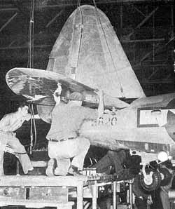
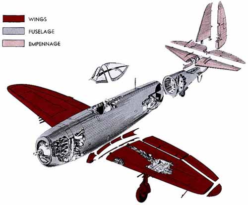
Design Analysis of the P-47 Thunderboltby Nicholas Mastrangelo Reprinted from the January 1945 issue of Industrial Aviation (author's collection)
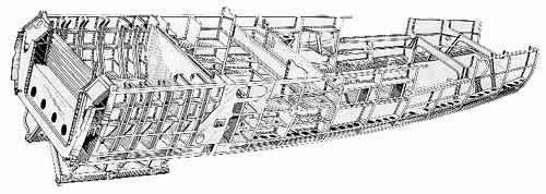
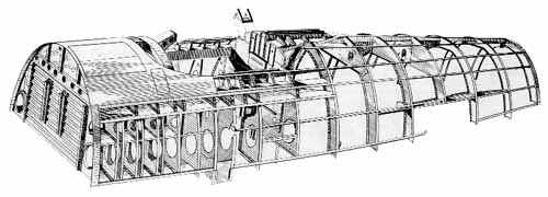
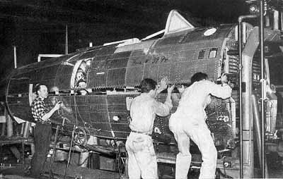
In the creation and conception of the Thunderbolt, her designer exploited every known advantage and adopted first, the efficient single-engine, single-fuselage with its least interrupted wing span, concentrated weight and reduced frontal area; secondly, the Kartveli-designed airfoil section (Republic S-3) representing a culmination of the knowledge gained by years of high speed airplane design; and lastly, its supercharging system, which occupies a considerable volume of the fuselage structure, designed to supply 52" Hg of manifold pressure up to stratosphere levels for its 2800 cu in engine. The 2000 hp, 18-cylinder, air-cooled engine presented a great majority of the problems and one of the first was created by the demand for the perfect supercharging duct system, one that would offer the most efficient, least interrupted air flow; this requirement was neatly solved by an "unorthodox procedure"; that is, the duct system was designed first and then around it, the fuselage. The return of many P-47s to "home base" with gaping wounds in the fuselage is sufficient evidence that structural efficiency was not sacrificed by this procedure. Since the conventional three-bladed propeller was not adaptable for the Thunderbolt installation, the four-bladed propeller was installed; the P-47, incidently, served as the first test stand for this propeller. Although the four-bladed propeller was an admirable solution to the power gearing of the engine, there remained the problem of landing gear height. If minimum ground clearance for the 12 ft diameter propeller had been maintained by the conventional landing gear, its suspension would have been too far outboard and would have necessitated either less ammunition or guns; if the same firing power were to be maintained, the installation of the armament would have created an inefficient cumbersome wing structure; hence, the first telescopic landing gear. Republic designed, the landing gear is 9" shorter when retracted and therefore allows correspondingly farther inboard suspension. In this manner, both heavy armament installation and efficient wing structure are retained. The installation of suitable fuel quantities was another of the major problems resulting from the adoption of the single fuselage and efficient turbo duct design and without detailing the development of the expansion of the internal fuel load of the P-47, it may be said, at present, that the latest Thunderbolt, details of which are not yet released, will have the greatest combat range of any pursuit airplane. The need for ingenuity did not end with the solution to these problems, however, for the Thunderbolt’s speed and natural habitat (above 30,000 ft) presented additional challenges. Ailerons "snatched and froze"; canopies could not be opened and control loads became excessive. These and other high-speed effects, which have now lost some of their mystery, were experienced during th P-47’s early high speed runs and as solutions, Republic equipped the Thunderbolt with blunt-nosed ailerons, jettisonable canopies, all-metal control surfaces and was the first airplane to reduce rudder pedal loads by use of balanced trim tabs. Fuselage The fuselage of the P-47 is of semi-monococque, all-metal, stressed-skin construction, composed of transverse bulkheads and longitudinal stringers. The main or forward structure is divided into top and lower halves to station 302˝, while the tail "cone" or fuselage aft section, comprising the fuselage aft of station 302˝, is constructed as a unit. The upper and lower main fuselage halves are bolted at reinforcing angles built into the parting surfaces of the structure and joggled extensions on the upper half frames are spliced by riveting to the lower half frames. Assembly of the fuselage is complete by joining the aft fuselage section to the main section at the 302˝ station. Here, the facing frames of the forward and aft sections are riveted and bolted while the skin extension of the aft section is butt jointed to the main section skin and riveted to the last frame of the forward section.
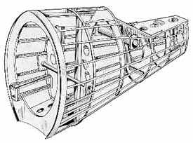
Major structural units of the fuselage, two wing supporting bulkheads, are contained in the main lower half section. Each of the two bulkheads is constructed around a pair of 3˝" wide E section steel beams which extend the width of the bulkheads and serve as cross-ties. The wing support hinges, which are forgings of X4340 steel, extend into each end of the cross-tie beams and are secured to the ties by 3/8" bolts. Forward or firewall bulkhead is faced with stainless steel sheet over alclad 24-ST ‘sheet of .091 gauge and the aft side is faced with similar flat sheet, reinforced by corrugated sheet and channel section, all of alclad 24-ST. The aft bulkhead incorporates the aft wing hinges. Except for the absence of stainless steel sheet facing and corrugated sheet, the structure is similar to that of the forward bulkhead. Lower outboard ends of both the wing hinge bulkheads support trapezoidal shaped forgings; longeron components are riveted to these forgings, thus establishing the foundation for the remainder of the lower half fuselage structure. This lower longeron extends the entire length of the forward fuselage section and provides support for the remaining transverse structural elements. Stringers are located at suitable intervals from the longeron to the angle-reinforced parting surface of the lower half structure. Lower half frame segments are riveted to longeron and stringers and then flush riveted skin of various gauges with additional reinforcing sheets at the wing hinge fitting openings and other high stressed areas complete the structure of the main lower half fuselage section.
The upper half forward fuselage section, though not as rugged as the lower half fuselage section, is constructed similar to the lower half section. The upper half forward bulkhead has, due to the absence of the 3˝" steel channel, less depth than the matching lower half and consequently is stepped back so as to present a flush surface on the aft face of the firewall. A corrugated sheet faced on either side extends to the upper engine mount cross-tie which is an angle of 24-ST. Since the structure above the engine mount cross-tie is the low stress area of the bulkhead, it is of single sheet thickness. Similar trapezoidal shaped forgings as employed in the bulkheads of the lower half section are bolted to the engine mount cross tie, to serve as the structural basis for the upper longeron. The upper fuselage half extension of the aft wing-hinge-support-bulkhead consists of .064" flanged segments, extending to the upper longeron, spliced with .064" splice plates to both faces of the bulkhead. Frame 180, representing the aft partition of the cockpit, unlike the wing hinge support bulkheads where the conditions are reversed, has rugged structure in the upper half section and flanged frame segment support in the lower half section. The additional ruggedness is due to the fact that this frame supports the aft armor plating. The remaining upper-half frames aft of 180 are flanged semicircular segments tied by stringers. The aft fuselage section, since it is constructed as a unit, employs complete frames and is tied by stringers in a fashion similar to the forward half structure. The tail wheel supporting frame is subjected to heavy landing loads and is therefore, considerably reinforced by vertical and horizontal extrusions and webs. This frame is also braced at the bottom by a box-like structure extending to frame 302˝. A transverse web is riveted along the upper area of the last three frames of the aft section, forming the support structure for the empennage.
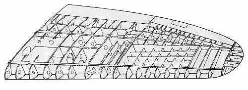
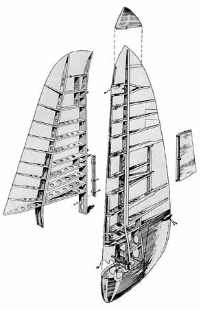
The wing of the P-47 is a full cantilever type employing 2 main spars and stressed skin and multicellular construction. It has a span of 41’, root chord of 109˝", mean aerodynamic chord of 87.46"; a 5.61 aspect ratio; an angle of incidence of +1° and a top surface dihedral of 4° . Angle of incidence and amount of dihedral are fixed.
Wing Construction Wing covering is butt fitted, flush riveted, stressed skin type and is reinforced by extruded angle stringers. The cut-out skin area which includes inspection, access and maintenance doors, as well as the larger cut-out areas of the landing gear wells and gun and ammunition bays is about 16% of the total main panel area; the high percentage is indicative of. the rigidity inherent in the prime structure of the wing.
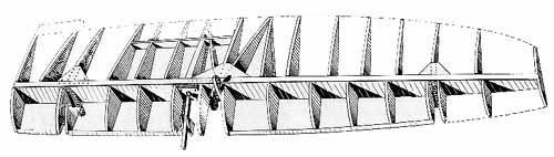
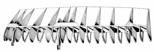
Main members of the wing are the two main spars which support attachment of the wing to the fuselage and three auxiliary spars, one each supporting the aileron and flap and the other supporting the landing gear. Main spars are constructed of E-shaped cap strips riveted to webs of varying thickness from a minimum of .032" for the outboard web of both spars to a maximum of .250" thickness for the inboard web of the forward main spar. Both main spars are reinforced at suitable intervals by extruded angles which also serve as anchors for frame installations. Inboard ends of the main spars of each wing are fitted with a pair of wing hinges which are pinned to the mating fuselage hinges by split bushings; tapered bolts expand these bushings to a tight fit, thus securing positive attachment. The aft auxiliary spars support the movable surfaces and are constructed of angle cap strips and webs of .072" to .025" thickness. The landing gear auxiliary spar, since it is subjected to landing loads, is of somewhat heavier construction—namely, .091" web and is reinforced similar to the main spars. Flanged ribs of alclad 24-ST are secured between spars at the angle stiffeners. Ribs vary from .051 to .032 with the exception of the root chord rib and gun bay partitioning ribs; the root chord rib is .064" and the gun bay partitioning ribs of .064". Nose and trailing edge ribs are flanged and are also of Alclad 24-ST. Aileron Ailerons of the P-47, representing about 11.4% of the total projected wing area, are Frise type, aerodynamically and dynamically balanced and are 16 in-lb overbalanced. They are hinged to steel forgings attached to the outboard auxiliary wing spar and are controlled by a system of push-pull rods; an all metal controllable trim tab is provided in the left aileron.
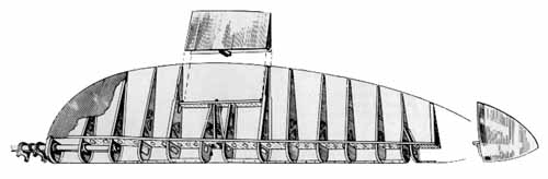
Flanged nose and tail ribs of 24-ST, are attached in staggered fashion to a main spar and alclad 24-ST sheet is flush riveted to spar and ribs. Forged aluminum alloy hinges of the aileron are attached to the outboard auxiliary wing spar. Landing Flaps Landing flaps of the P-47, representing 13% of the total projected wing area, are NACA slotted trailing edge type. They are hydraulically operated, receiving pressure and fluid from the hydraulic system and during extension move first aft and then down and during retraction move first up and then forward; this movement, actuated by three trapezoidal linkage hinges, insures perfect positioning of the flap against the main panel, thereby maintaining the proper airfoil section. The linkage hinges are synchronized by attachment to a torque tube and the assembly is attached to the inboard auxiliary wing spar. Independent units are synchronized by hydraulic pressure. Flaps are pinned to the flap linkage assembly hinges with standard bolts.
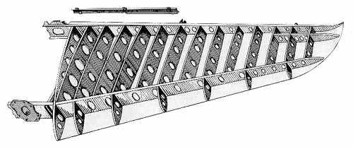
The double cambered external surface of the flap is alclad 24-ST riveted to flanged nose and tail ribs which attach to a spar of 24-ST in symmetrical order; additional lightened reinforcing nose ribs are provided between each pair of the flanged nose ribs. Compressible Recovery Flaps Late P-47 models have incorporated flaps for the purpose of aiding in recovery from dives of compressibility speeds. These surfaces are operated by two electric, reversible, intermittent motors synchronized by flexible shafting. Magnetic brake and clutch assemblies are incorporated to prevent overtravel and switches limit the flap extension to 22˝° so as to hold "gs" to a safe value during "pull-outs." The compressible recovery flaps are .188" flat sheets of 24-ST and are hinged at the landing gear auxiliary spar, located just forward of the landing flaps. In the retracted position, they are flush with the lower wing surface contour. Empennage The empennage of Thunderbolt is a full cantilever structure with a total projected area of 81.45 sq. ft.
All surfaces are metal covered and the elevators and rudder are equipped with controllable trim tabs of all metal construction. Fin and the horizontal stabilizer assembly of the P-47 are of similar construction, both assemblies employing flanged ribs between a forward and aft spar and flanged nose ribs with 24-ST alclad skin. Hinges for the tail surfaces and chain-actuated worm and screw units for trim tab operation are attached to the aft spars of both assemblies.
Fin spars straddle the horizontal stabilizer assembly spars and at this junction are bolted to common splice plates thus forming a complete stabilizer unit. To install the complete stabilizer unit to the fuselage, the stabilizer forward spar is bolted to fittings on the horizontal web of the aft fuselage section and the aft spar is bolted to a plate fastened to the last frame of the fuselage.
Rudder The rudder is Handley-Page type having static and dynamic balance. Dynamic balance coefficient is less than zero and static balance is 25 in-lb under balance. The rudder trim tab provided dynamic balance as well as selective trim.
As all other surfaces of the P-47, this control surfaces is alclad aluminum alloy covered and employs a main spar and flanged ribs of 24-ST alloy. Elevators Elevators are of Handley-Page type with a dynamic balance coefficient of zero or less and static balance of 10 in-lb underbalanced. The elevators of the Thunderbolt are manufactured singly and are assembled into a unit by splicing torque tubes extending from the inboard nose sections of the elevators.
The entire surfaces of the elevators are 24-ST alloy covered and constructed of a spar and stamped, flanged ribs; the torque tubes are secured to the first three inboard nose ribs of each elevator. Elevators are hinged to the rear stabilizer spar and a torque-tube-pivot is provided by roller bearings staked in hinge brackets which are attached to the rear fuselage frame. The last control rod is linked to the elevator at a bracket that is part of the torque tube splice sleeve. Power Plant The power plant of the P-47 is a Pratt & Whitney R-2800, air-cooled, radial, twin row, 2000 hp engine. It is 72ľ" long, 52 ˝" in diameter and weighs more than a ton. It has a bore of 5.75", stroke of 6.00" and a displacement of 2804 cu in; the compression ratio is 6.7:1 and propeller drive ratio .500:1. Engine is attached by Lord mounts and drives either electric or hydraulic controlled constant-speed 4-bladed propeller assemblies. The NACA type cowling consists of a group of four quick detachable panels fastened to supporting rings attached to the rocker box covers of the engine. Hydraulically operated flaps for controlling exits of cooling air are provided at the upper rear section of the secondary engine cowling. Normal fuel load is carried in two self-sealing fuel tanks fitted with baffles to minimize surge; a main tank is installed between the wing hinge supporting bulkheads and an auxiliary tank is installed directly aft of the rear wing hinge supporting bulkhead. To prevent vapor lock at high altitude, both tanks are equipped with electrically operated booster pumps which are of sufficient capacity to insure adequate fuel pressure and flow in the event of failure of a type G-9 engine-driven fuel pump. External fuel is carried in combat or ferrying tanks attached to bomb shackles in the belly and/or wing. These tanks are pressurized by the exhaust of the vacuum pump. Lubricating oil is carried in a hopper-type magnesium tank of 28.6 U.S. gal capacity, strapped to supports on the engine mount. A pendulum is incorporated in the tank to insure adequate lubrication for inverted flights of limited duration. Oil temperature is regulated by two radiators mounted below the engine; surge valves permit cold oil to bypass the radiators. Each radiator has an air scoop with an outlet door controlled by an electrically operated motor; the doors operate simultaneously from the one motor. The supercharging system of the P-47 airplane is designed to supply 52" Hg manifold pressure (considerably more for War Emergency Power) to the engine up to stratosphere levels. Diagram of Supercharging System The exhaust driven turbine is approximately 22 ft aft of the propeller and is supported by a ring attached to the lower longerons. The exhaust gases are collected by two rings, one each for the left and right bank of cylinders and directed to the nozzle box of the turbine through shrouded exhaust piping along either side of the airplane beneath the fuselage. Spent gas escapes through a stainless steel flight hood which extends below the fuselage. Ram air is piped through ducts under the fuselage extending from the primary cowling to the impeller-inlet of the turbine; after supercharging, the air is scooped to the intercooler then piped along either side of the fuselage and directed to a single duct above the carburetor. A considerable volume of the "ram" is conducted to the intercooler in order to lower the temperature of supercharged air. Electric-motor-controlled doors of the intercooler exit ducts on both sides of the fuselage vary the flow of cooling air through the intercooler. Supercharging is controlled to maintain the manifold pressure value selected by the pilot, by means of an oil operated supercharger regulator. The regulator, through linkage, varies the position of waste gates in the exhaust pipes just aft of the collector rings and thus controls the volume of exhaust gases directed to the nozzle box of the turbine. The position of a piston in the regulator, is balanced by exhaust pressure and a compression spring; the spring is mechanically loaded to correspond to the desired exhaust pressure valve by a supercharger lever in the cockpit. When the exhaust pressure varies from the selected value, the piston moves in the direction of the greater pressure and opens a port admitting pressurized lubricating oil to that chamber of the regulator which will affect the movement of the waste gates in the proper direction to balance the piston at the neutral position. Interconnected Engine Controls In order to minimize pilots attention to engine controls, the propeller, boost, and throttle levers of the P-47 may be interconnected and moved as a single lever with power and rpm correlated through the full range of the control quadrant. Correlation is mechanical. The propeller lever is correlated by the use of a cam; throttle and boost levers are correlated by adjustment of conventional push-pull rods. Controls may be disconnected by releasing a simple spring loaded clip on the throttle lever. Water lnjection Used Diagram of Water Injection Regulator & Hydraulic System To meet the demands for a higher emergency rating and to safeguard the engine from detonation when operated at considerably above the military power, water injection has been applied to the Thunderbolt’s power plant. Water is pumped from a 30 gal tank strapped to the firewall and is admitted through a water regulator by operation of a solenoid valve. Pressurized water beyond the regulator resets carburetor mixture so that the fuel-air ratio is decreased thereby increasing power without a corresponding rise in manifold pressure. The higher increase in power, however, is developed by high manifold pressure accomplished through a boost reset mechanism also actuated by water pressure; the reset overrides the supercharger regulator setting of the waste gates, therefore permitting the turbo to develop the higher rpms required to maintain the War Emergency Rating manifold pressure. Main Landing Gear The full cantilever, hydraulically-controlled main landing gear of this airplane consists of independent right and left hand units of air-oil combination shock strut assemblies and extra high pressure cast magnesium wheels of drop center rim type. A box-like structure of four cast magnesium plates, two of which serve as trunnions, supports each shock strut assembly. The box assembly fits into a well, formed by rib 86, rib 104, and the landing gear auxiliary spar, and is supported by four bolts through each of the ribs and adjacent plates. Before the gear starts its retraction cycle, hydraulic pressure is applied to withdraw a nitrided steel downlocking pin from a housing in the downlocking arm of the strut; a mechanically operated sequence valve is then opened to admit pressure to the landing gear retraction cylinder. During retraction, the shock strut piston is telescoped to the bottoming position so that at the completion of the "up" cycle the gear will fit into a well which is 9" shorter than would be necessary for conventional "up-positioning" of the gear. The telescoping is accomplished by the "geometry" of the mechanism which employs a shrinkage strut or rod; one end of this rod is attached to the shock strut piston and the other pivoted about an axis outboard and below that of the landing gear pivot axis. Geometrically, the shock strut and shrinkage strut can be considered as radial elements from different radii terminating at the lower end of the shock strut piston housing and the lower end of the piston respectively. The radii (landing gear and shrinkage strut pivot axes) are spaced so that the difference in the loci at approximately 0° (landing gear down) is almost zero and the difference between loci at approximately - 90° (landing gear up) is about 9". As the piston telescopes, the air in the air-oil chamber of the shock strut is displaced by the oil and is transferred to an auxiliary air chamber above the air-oil chamber in the strut. An air valve, actuated by a push rod following a cam track above the strut, opens the auxiliary air chamber. Armament The four .50 cal machine guns in each wing of the P-47 are secured in the gun bays to Republic-designed mounts. Front mounts are conical-shaped and the guns are locked to these by rotating the locking ring of the gun bracket assembly; the rear-mounts are locked by simple levers which are part of the rear mount assemblies. Ammunition of more than 350 rounds per gun may he carried in the bays just outboard of the gun bays. Bombs and rocket tubes are supported in conventional shackles under the wing. The pilot is protected from enemy gun fire by face hardened 3/8" armor plate located in the forward and aft ends of the cockpit. The area above the front armor plate is protected by 1˝" bullet resistant glass. | ||||||||||||||||||||||||||||||||||||||||||||||||||||||||||||||||||||||
|
All material not specifically credited is Copyright © by Randy Wilson.
All rights reserved.
|